Wiring Diagram Symbols : Electrical Symbols Composite Assemblies - A wiring diagram may include the wirings of a vehicle.. A resistor will be represented with a series of squiggles symbolizing the restriction of current flow. A car wiring diagram is a map. Electrical symbols or electronic circuits are virtually represented by circuit diagrams. Electrical … electrical schematic symbols. The symbols listed in this handbook were collected after much research by the technical staff of cleveland institute of electronics, inc.
(1) if the direction of change is not obvious, it may be indicated by an arrowhead on the outline of the symbol. Use the legend to understand what each symbol on the circuit means. There are some standard symbols to represent the components in a circuits. Variety of electrical wiring schematic symbols. This article gives some of the frequently used symbols for drawing the circuits.
Diagram How To Read Auto Wiring Diagram Symbols Full Version Hd Quality Diagram Symbols Piediagram Mbreporter It from tonetastic.info Electrical … electrical schematic symbols. Electrical symbols or electronic circuits are virtually represented by circuit diagrams. Just as with a road map, you will need to know a few basic symbols so you can figure out where you're going. A car wiring diagram is a map. Note the switch symbol displays an open or closed circuit path, which is what an actual switch performs. An electronic symbol is a pictogram used to represent various electrical and electronic devices or functions, such as wires, batteries, resistors, and transistors, in a schematic diagram of an electrical or electronic circuit.these symbols are largely standardized internationally today, but may vary from country to country, or engineering discipline, based on traditional conventions. In wiring diagrams, a user is not restricted to a single. 100+ electrical & electronic circuit symbols.
This is a perfect tool for engineers and architects to create and analyze complex electrical systems.
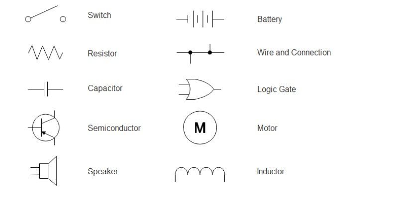
Most symbols used on a wiring diagram look like abstract versions of the real objects they represent. It reveals the components of the circuit as simplified forms, and also the power as well as signal links between the devices. Here are some of the standardized, basic schematic symbols for various components. Note the switch symbol displays an open or closed circuit path, which is what an actual switch performs. 100+ electrical & electronic circuit symbols. Allows current flow in one direction, but also can flow in the reverse direction when above breakdown voltage. Launch edrawmax on your computer. A wiring diagram is a sort of schematic which uses abstract pictorial icons to reveal all the interconnections of parts in a system. There are several other electrical wiring symbols used in residential and commercial wiring, but the above list of symbols are the important ones. The index lists components by general classification. Standard home wiring diagram symbols. The following table lists the most important symbols along with their names. A wiring diagram may include the wirings of a vehicle.
It reveals the components of the circuit as simplified forms, and also the power as well as signal links between the devices. (1) if the direction of change is not obvious, it may be indicated by an arrowhead on the outline of the symbol. As you go through various parallax microcontroller tutorials, you will see schematics describing the circuits to be built. This article gives some of the frequently used symbols for drawing the circuits. A resistor will be represented with a series of squiggles symbolizing the restriction of current flow.
Wiring Diagram A Comprehensive Guide Edrawmax Online from images.edrawmax.com The index lists components by general classification. There are some standard symbols to represent the components in a circuits. For example, how the horns are powered and connected to the controller on your steering wheel. These electrical and electronic circuit symbols are generally used for drawing schematic diagram. (1) if the direction of change is not obvious, it may be indicated by an arrowhead on the outline of the symbol. Click the icon of basic electrical to open the library that includes all symbols for making electrical diagrams. An extensive collection of electrical diagram templates can be found in the electrical engineering category. Typical electrical drawing symbols and conventions.
A wiring diagram may include the wirings of a vehicle.
A wiring diagram is a sort of schematic which uses abstract pictorial icons to reveal all the interconnections of parts in a system. An extensive collection of electrical diagram templates can be found in the electrical engineering category. November 20, 2020 1 margaret byrd. In wiring diagrams, a user is not restricted to a single. Wiring diagrams use an array of special symbols that represent various circuit elements like, switches, bulbs, electric outlets, breakers, smoke detectors, and many more. Automotive electrical diagrams provide symbols that represent circuit component functions. (1) if the direction of change is not obvious, it may be indicated by an arrowhead on the outline of the symbol. Symbols that represent the components in the circuit, and also lines that stand for the links in between them. Variety of electrical wiring schematic symbols. As you go through various parallax microcontroller tutorials, you will see schematics describing the circuits to be built. These electrical schematic symbols will help you to identify parts when working with an electrical schematic. I'm an auto technician for over twenty years, i've always loved the electrical side of auto repair. It reveals the components of the circuit as simplified forms, and also the power as well as signal links between the devices.
Here are some of the standardized, basic schematic symbols for various components. Lighting system description page section# # of pages 1. Aviation drawings drawing symbols how to read a schematic learn wiring installation diagrams classroom poster electrical systems aircraft diagram xn 7088 boeing simplified part 2. Here is the wiring symbol legend, which is a detailed documentation of common symbols that are used in wiring diagrams, home wiring plans, and electrical wiring blueprints. The symbols listed in this handbook were collected after much research by the technical staff of cleveland institute of electronics, inc.
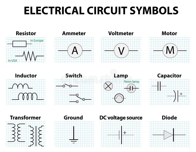
Common Circuit Diagram Symbols Stock Vector Illustration Of Circuit Motor 68934130 from thumbs.dreamstime.com A car wiring diagram is a map. Click the icon of basic electrical to open the library that includes all symbols for making electrical diagrams. A resistor will be represented with a series of squiggles symbolizing the restriction of current flow. Here is the wiring symbol legend, which is a detailed documentation of common symbols that are used in wiring diagrams, home wiring plans, and electrical wiring blueprints. I'm an auto technician for over twenty years, i've always loved the electrical side of auto repair. An extensive collection of electrical diagram templates can be found in the electrical engineering category. 100+ electrical & electronic circuit symbols. Wiring diagrams use simplified symbols to represent switches, lights, outlets, etc.
Note the switch symbol displays an open or closed circuit path, which is what an actual switch performs.
100+ electrical & electronic circuit symbols. Most symbols used on a wiring diagram look like abstract versions of the real objects they represent. A photographic layout would reveal extra information of the physical appearance, whereas a wiring diagram uses an extra symbolic symbols to highlight affiliations over physical look. Variety of electrical wiring schematic symbols. The index lists components by general classification. Because the electronics industry has not adopted a single symbology standard, cie has included the most frequently used symbols that represent each component. Note the switch symbol displays an open or closed circuit path, which is what an actual switch performs. The following table lists the most important symbols along with their names. An extensive collection of electrical diagram templates can be found in the electrical engineering category. Just as with a road map, you will need to know a few basic symbols so you can figure out where you're going. Typical electrical drawing symbols and conventions. A resistor will be represented with a series of squiggles symbolizing the restriction of current flow. Symbols that represent the components in the circuit, and also lines that stand for the links in between them.