As part of your design process, you'll need to start with a block diagram, circuit schematic, and eventually a PCB layout
Home
› Ladder Logic Diagram Examples : Ladder Diagram | Schematic Diagram | Wiring Diagram | Electrical Academia / Jun 06, 2018 · logic gates using plc programming explained with ladder diagram march 25, 2021 june 6, 2018 by dipali chaudhari as we all know, logic gate is a building block for the digital circuit.
Ladder Logic Diagram Examples : Ladder Diagram | Schematic Diagram | Wiring Diagram | Electrical Academia / Jun 06, 2018 · logic gates using plc programming explained with ladder diagram march 25, 2021 june 6, 2018 by dipali chaudhari as we all know, logic gate is a building block for the digital circuit.
Ladder Logic Diagram Examples : Ladder Diagram | Schematic Diagram | Wiring Diagram | Electrical Academia / Jun 06, 2018 · logic gates using plc programming explained with ladder diagram march 25, 2021 june 6, 2018 by dipali chaudhari as we all know, logic gate is a building block for the digital circuit.. Notice that the unlatch is within the same branch as the pf1:o.clearfaults instruction that will be energized once the reset is set. Aug 19, 2018 · the ladder diagram is the universal programming language of plc. Feb 09, 2015 · ladder logic was designed to have the same look and feel as electrical ladder diagrams, but with ladder logic, the physical contacts and coils are replaced with memory bits. In the ladder diagram, the programming language that used to create the program to control the plc system is known as 'ladder diagram language. Ladder logic was originally a written method to document the design and construction of relay racks as used in manufacturing and process control.
Sep 04, 2017 · ladder logic (also known as ladder diagram or ld) is a programming language used to program a plc (programmable logic controller). For this program, the relay logic's ladder diagram is duplicated with ladder logic; Ld is one of the oldest programming languages for plc. Each device in the relay rack would be represented by a symbol on the ladder diagram with connections between those devices shown. In the ladder diagram, the programming language that used to create the program to control the plc system is known as 'ladder diagram language.
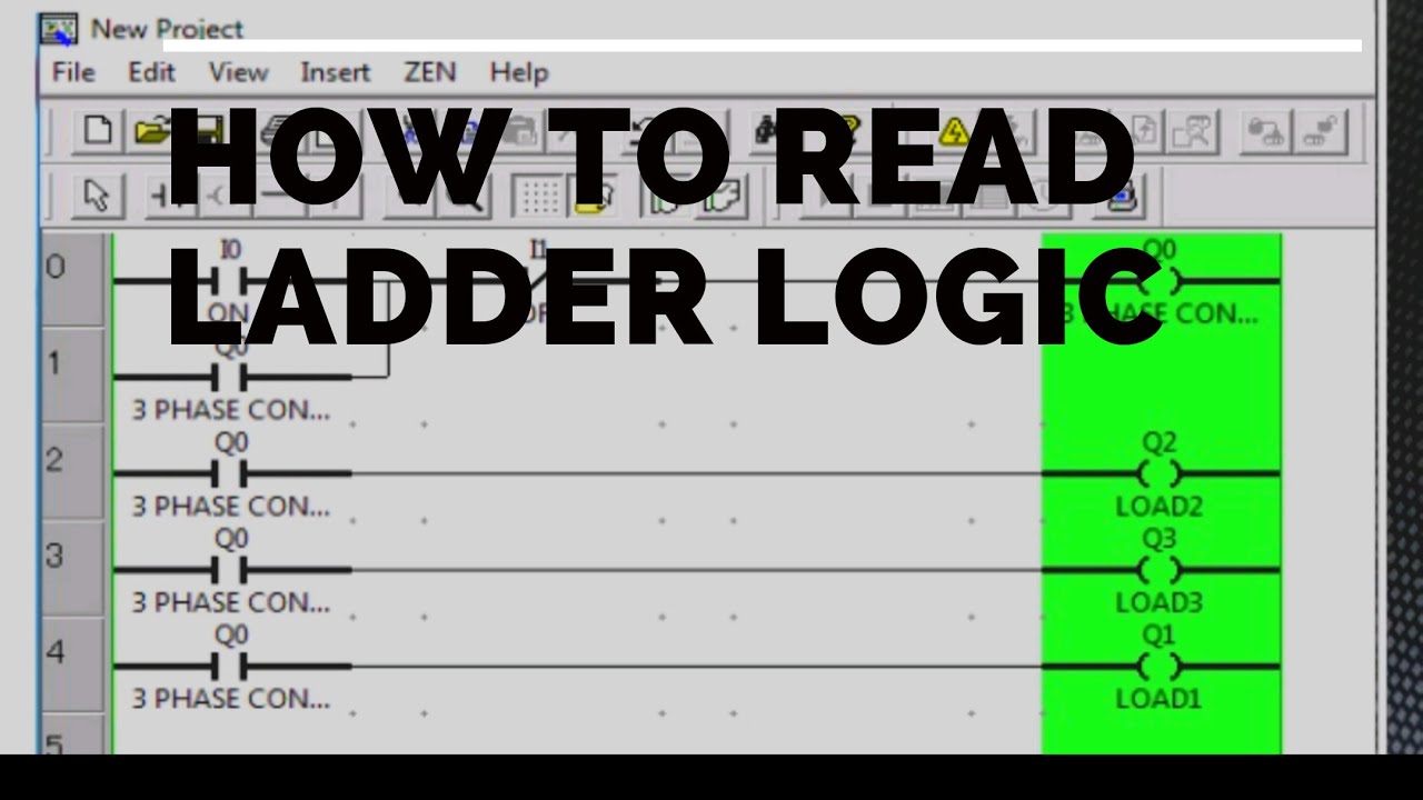
how to read ladder logic diagram - YouTube from i.ytimg.com Ld is one of the oldest programming languages for plc. The most common language used to program plcs is ladder diagram (ld), also known as relay ladder logic (rll). But, these days the terms ladder diagram, ladder logic diagram, ladder drawing, ladder control, ladder circuit, control logic diagram and logic diagram (to name a few) are all used to describe relay logic circuits and ladder logic programming. For this program, the relay logic's ladder diagram is duplicated with ladder logic; Jun 06, 2018 · logic gates using plc programming explained with ladder diagram march 25, 2021 june 6, 2018 by dipali chaudhari as we all know, logic gate is a building block for the digital circuit. A ladder logic example of a trafic light can, as an example, vary a lot. In the ladder diagram, the programming language that used to create the program to control the plc system is known as 'ladder diagram language. It is a graphical plc programming language which expresses logic operations with symbolic notation.
One other thing that causes good plc ladder logic examples to be so hard to find, is that ladder logic often is brand specific.
Especially because the names of the ladder logic examples often are confusing and even misguiding. In the ladder diagram, the programming language that used to create the program to control the plc system is known as 'ladder diagram language. Each device in the relay rack would be represented by a symbol on the ladder diagram with connections between those devices shown. Jun 06, 2018 · logic gates using plc programming explained with ladder diagram march 25, 2021 june 6, 2018 by dipali chaudhari as we all know, logic gate is a building block for the digital circuit. Sep 04, 2017 · ladder logic (also known as ladder diagram or ld) is a programming language used to program a plc (programmable logic controller). Notice that the unlatch is within the same branch as the pf1:o.clearfaults instruction that will be energized once the reset is set. For this program, the relay logic's ladder diagram is duplicated with ladder logic; A ladder logic example of a trafic light can, as an example, vary a lot. Jun 27, 2015 · ladder logic examples can be hard to find, though. One other thing that causes good plc ladder logic examples to be so hard to find, is that ladder logic often is brand specific. The most common language used to program plcs is ladder diagram (ld), also known as relay ladder logic (rll). But, these days the terms ladder diagram, ladder logic diagram, ladder drawing, ladder control, ladder circuit, control logic diagram and logic diagram (to name a few) are all used to describe relay logic circuits and ladder logic programming. It is a graphical plc programming language which expresses logic operations with symbolic notation.
A ladder logic example of a trafic light can, as an example, vary a lot. Each device in the relay rack would be represented by a symbol on the ladder diagram with connections between those devices shown. One other thing that causes good plc ladder logic examples to be so hard to find, is that ladder logic often is brand specific. But, these days the terms ladder diagram, ladder logic diagram, ladder drawing, ladder control, ladder circuit, control logic diagram and logic diagram (to name a few) are all used to describe relay logic circuits and ladder logic programming. It has a short abbreviation as 'ld' and also known as 'ladder logic'.
Ladder Logic Programming Examples - PLC Practical Problems from cdn.instrumentationtools.com Each device in the relay rack would be represented by a symbol on the ladder diagram with connections between those devices shown. Feb 09, 2015 · ladder logic was designed to have the same look and feel as electrical ladder diagrams, but with ladder logic, the physical contacts and coils are replaced with memory bits. The most common language used to program plcs is ladder diagram (ld), also known as relay ladder logic (rll). Ld is one of the oldest programming languages for plc. It has a short abbreviation as 'ld' and also known as 'ladder logic'. Notice that the unlatch is within the same branch as the pf1:o.clearfaults instruction that will be energized once the reset is set. Especially because the names of the ladder logic examples often are confusing and even misguiding. One other thing that causes good plc ladder logic examples to be so hard to find, is that ladder logic often is brand specific.
Jun 06, 2018 · logic gates using plc programming explained with ladder diagram march 25, 2021 june 6, 2018 by dipali chaudhari as we all know, logic gate is a building block for the digital circuit.
Jun 06, 2018 · logic gates using plc programming explained with ladder diagram march 25, 2021 june 6, 2018 by dipali chaudhari as we all know, logic gate is a building block for the digital circuit. Each device in the relay rack would be represented by a symbol on the ladder diagram with connections between those devices shown. Aug 19, 2018 · the ladder diagram is the universal programming language of plc. The most common language used to program plcs is ladder diagram (ld), also known as relay ladder logic (rll). Feb 09, 2015 · ladder logic was designed to have the same look and feel as electrical ladder diagrams, but with ladder logic, the physical contacts and coils are replaced with memory bits. It is a graphical plc programming language which expresses logic operations with symbolic notation. Sep 04, 2017 · ladder logic (also known as ladder diagram or ld) is a programming language used to program a plc (programmable logic controller). Ld is one of the oldest programming languages for plc. In the ladder diagram, the programming language that used to create the program to control the plc system is known as 'ladder diagram language. It has a short abbreviation as 'ld' and also known as 'ladder logic'. Ladder logic was originally a written method to document the design and construction of relay racks as used in manufacturing and process control. One other thing that causes good plc ladder logic examples to be so hard to find, is that ladder logic often is brand specific. Especially because the names of the ladder logic examples often are confusing and even misguiding.
Aug 19, 2018 · the ladder diagram is the universal programming language of plc. The most common language used to program plcs is ladder diagram (ld), also known as relay ladder logic (rll). But, these days the terms ladder diagram, ladder logic diagram, ladder drawing, ladder control, ladder circuit, control logic diagram and logic diagram (to name a few) are all used to describe relay logic circuits and ladder logic programming. For this program, the relay logic's ladder diagram is duplicated with ladder logic; Jun 06, 2018 · logic gates using plc programming explained with ladder diagram march 25, 2021 june 6, 2018 by dipali chaudhari as we all know, logic gate is a building block for the digital circuit.
plc-program-for-bottle-filling-ladder-logic | Ladder logic, Electrical circuit diagram ... from i.pinimg.com One other thing that causes good plc ladder logic examples to be so hard to find, is that ladder logic often is brand specific. In the ladder diagram, the programming language that used to create the program to control the plc system is known as 'ladder diagram language. It has a short abbreviation as 'ld' and also known as 'ladder logic'. Notice that the unlatch is within the same branch as the pf1:o.clearfaults instruction that will be energized once the reset is set. But, these days the terms ladder diagram, ladder logic diagram, ladder drawing, ladder control, ladder circuit, control logic diagram and logic diagram (to name a few) are all used to describe relay logic circuits and ladder logic programming. It is a graphical plc programming language which expresses logic operations with symbolic notation. Sep 04, 2017 · ladder logic (also known as ladder diagram or ld) is a programming language used to program a plc (programmable logic controller). A ladder logic example of a trafic light can, as an example, vary a lot.
Especially because the names of the ladder logic examples often are confusing and even misguiding.
For this program, the relay logic's ladder diagram is duplicated with ladder logic; Sep 04, 2017 · ladder logic (also known as ladder diagram or ld) is a programming language used to program a plc (programmable logic controller). Each device in the relay rack would be represented by a symbol on the ladder diagram with connections between those devices shown. Ladder logic was originally a written method to document the design and construction of relay racks as used in manufacturing and process control. It has a short abbreviation as 'ld' and also known as 'ladder logic'. A ladder logic example of a trafic light can, as an example, vary a lot. Notice that the unlatch is within the same branch as the pf1:o.clearfaults instruction that will be energized once the reset is set. Jun 06, 2018 · logic gates using plc programming explained with ladder diagram march 25, 2021 june 6, 2018 by dipali chaudhari as we all know, logic gate is a building block for the digital circuit. Jun 27, 2015 · ladder logic examples can be hard to find, though. But, these days the terms ladder diagram, ladder logic diagram, ladder drawing, ladder control, ladder circuit, control logic diagram and logic diagram (to name a few) are all used to describe relay logic circuits and ladder logic programming. Feb 09, 2015 · ladder logic was designed to have the same look and feel as electrical ladder diagrams, but with ladder logic, the physical contacts and coils are replaced with memory bits. It is a graphical plc programming language which expresses logic operations with symbolic notation. Especially because the names of the ladder logic examples often are confusing and even misguiding.