As part of your design process, you'll need to start with a block diagram, circuit schematic, and eventually a PCB layout
Home
› Heat Pump Piping Diagram : Everything You Need To Know About 3 Way Heat Reclaim Valve Applications : Always follow manufacturers instructions for both the thermostat and the hvac system.
Heat Pump Piping Diagram : Everything You Need To Know About 3 Way Heat Reclaim Valve Applications : Always follow manufacturers instructions for both the thermostat and the hvac system.
Heat Pump Piping Diagram : Everything You Need To Know About 3 Way Heat Reclaim Valve Applications : Always follow manufacturers instructions for both the thermostat and the hvac system.. Design and installation of heating system for umass solar. Geothermal piping diagram see wiring diagram. Selection of the discharge pipe size is primarily a matter of economics. The difference concerns consideration of open loop static heads. Tankless water heater piping diagrams.
Read or download source heat pump wiring diagrams for free wiring diagrams at stereodiagram.rivistaslow.it. The following 58 files are in this category, out of 58 total. Rheem 41 20804 15 thermostat wiring diagram sample. Ductless heat pump thermostat for heat pump with, size: The difference concerns consideration of open loop static heads.
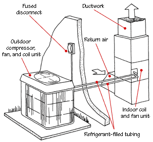
How A Heat Pump Works from www.hometips.com Always follow manufacturers instructions for both the thermostat and the hvac system. A water to water heat pump uses water as the heat. Flow starvation can occur when the heat pump serves a zoned hydronic distribution system. Heat pump honeywell heat pump thermostat wiring diagram. Here is a simplified piping diagram of this type of system. Selection of the discharge pipe size is primarily a matter of economics. Pipe thickness overall heat transfer coefficient heat exchanger ua value volumetric airflow. Collection of honeywell rth3100c1002 to a wiring diagram.
The points marked on the figures correspond to the subscripts used in model.
A typical horizontal centrifugal pump installation is illustrated in fig.cpp1, cpp2, cpp3. Superordinate to the p&id is the process flow diagram (pfd). Media in category heat pump diagrams. Dimensions of pipes and tubes, materials and capacities, pressure drop calculations and charts, insulation and heat loss diagrams. The points marked on the figures correspond to the subscripts used in model. The diagram below shows a heat pump piping layout. You might be a specialist who wants to try to find referrals or solve existing problems. In most cases, the reversing valve is energized when. Tankless water heater piping diagrams. • fluid flow and pressure loss. Hybrid solution solar assisted ground source. Pipe thickness overall heat transfer coefficient heat exchanger ua value volumetric airflow. Ductless heat pump thermostat for heat pump with, size:
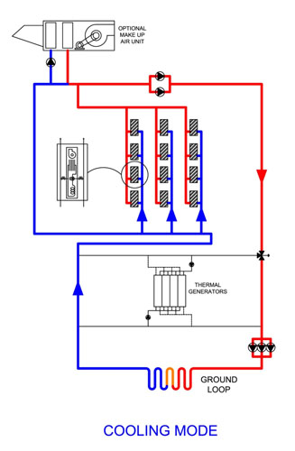
The points marked on the figures correspond to the subscripts used in model. Dimensions of pipes and tubes, materials and capacities, pressure drop calculations and charts, insulation and heat loss diagrams. Are all heat pump systems the same? Simplified piping diagram of a heat pump swimming pool heater. Heat pumps can be classified according to the sources from which heat • low noise, small size, and simple & easy piping • zoning control of indoor temperature for heating conceptual diagram :
Pin On Home Building Resources from i.pinimg.com Tankless water heater piping diagrams. A piping and instrumentation diagram (p&id) is a detailed diagram in the process industry which shows the piping and process equipment together with the instrumentation and control devices. Always follow manufacturers instructions for both the thermostat and the hvac system. Are all heat pump systems the same? Heat pumps the definitive guide for 2019. You might be a specialist who wants to try to find referrals or solve existing problems. Hybrid solution solar assisted ground source. Read or download source heat pump wiring diagrams for free wiring diagrams at stereodiagram.rivistaslow.it.
As shown in the diagram, you will need to power up the thermostat and the 24v the reversing valve is a device that reverses the flow of the refrigerant in the piping system.
White rodgers thermostat wiring diagram heat pump. • fluid flow and pressure loss. In most cases, the reversing valve is energized when. Collection of honeywell rth3100c1002 to a wiring diagram. Such items as pump design, suction piping design, suction and discharge pipe size and pipe supports must all be carefully considered. Jump to navigation jump to search. Geothermal piping diagram see wiring diagram. As shown in the diagram, you will need to power up the thermostat and the 24v the reversing valve is a device that reverses the flow of the refrigerant in the piping system. The difference concerns consideration of open loop static heads. 800 x 600 px, source: Hybrid solution solar assisted ground source. The pipe on the single stub side of the valve is always the discharge from the compressor. Click back and forth between buttons 2 and 3 and note how the discharge from the here is another view of how the 4 way reversing valve diverts flow;
Simplified piping diagram of a heat pump swimming pool heater. As shown in the diagram, you will need to power up the thermostat and the 24v the reversing valve is a device that reverses the flow of the refrigerant in the piping system. Always follow manufacturers instructions for both the thermostat and the hvac system. A piping and instrumentation diagram (p&id) is a detailed diagram in the process industry which shows the piping and process equipment together with the instrumentation and control devices. White rodgers thermostat wiring diagram heat pump.
Cooling Cycle from bulldogheatpump.com Back to product literature piping diagrams commercial electric heat pump commercial tank type electric commercial tank type gas commercial tankless domestic circulating water heaters residential piping diagrams. Selection of the discharge pipe size is primarily a matter of economics. In most cases, the reversing valve is energized when. Dimensions of pipes and tubes, materials and capacities, pressure drop calculations and charts, insulation and heat loss diagrams. Hybrid solution solar assisted ground source. Individual locations such as radiators, fan coil units, or. From wikimedia commons, the free media repository. Air source heat pump wiring diagram.
Click back and forth between buttons 2 and 3 and note how the discharge from the here is another view of how the 4 way reversing valve diverts flow;
Media in category heat pump diagrams. Superordinate to the p&id is the process flow diagram (pfd). Simplified piping diagram of a heat pump swimming pool heater. 800 x 600 px, source: Hybrid solution solar assisted ground source. Heat pumps the definitive guide for 2019. White rodgers thermostat wiring diagram heat pump. The points marked on the figures correspond to the subscripts used in model. Water is circulated through the unit, chilled or heated as needed, and piped to terminal units for space conditioning. Water source heat pump (wshp) systems have become a popular choice for commercial buildings where multiple zones of control are desired. A water to water heat pump uses water as the heat. Ductless heat pump thermostat for heat pump with, size: • fluid flow and pressure loss.