As part of your design process, you'll need to start with a block diagram, circuit schematic, and eventually a PCB layout
Home
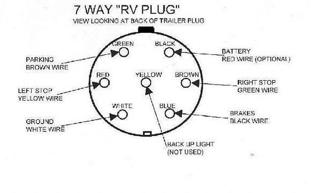
› Wiring A Trailer With Brakes : Installing Electric Brakes on Your Trailer | R and P Carriages | Cargo, Utility, Dump, equipment ... : 7 way plug wiring diagram standard wiring* post purpose wire color tm park light green (+) battery feed black rt right turn/brake light brown lt left turn/brake light red s trailer electric brakes blue gd ground white a accessory yellow this is the most common (standard) wiring scheme for rv plugs and the one used by major auto manufacturers today.
Wiring A Trailer With Brakes : Installing Electric Brakes on Your Trailer | R and P Carriages | Cargo, Utility, Dump, equipment ... : 7 way plug wiring diagram standard wiring* post purpose wire color tm park light green (+) battery feed black rt right turn/brake light brown lt left turn/brake light red s trailer electric brakes blue gd ground white a accessory yellow this is the most common (standard) wiring scheme for rv plugs and the one used by major auto manufacturers today.
Wiring A Trailer With Brakes : Installing Electric Brakes on Your Trailer | R and P Carriages | Cargo, Utility, Dump, equipment ... : 7 way plug wiring diagram standard wiring* post purpose wire color tm park light green (+) battery feed black rt right turn/brake light brown lt left turn/brake light red s trailer electric brakes blue gd ground white a accessory yellow this is the most common (standard) wiring scheme for rv plugs and the one used by major auto manufacturers today.. It reveals the parts of the circuit as streamlined forms, as well as the power and signal connections in between the gadgets. The brake controller comes with a wiring harness that is the kind you have to splice into your vehicle's wiring. Assortment of electric trailer brake wiring schematic. There are wires extending from the switch and using a circuit tester, you can find the wire that has power when the brake pedal is pressed. The white wire must be attached to the trailer for the grounding and power supply of the lights.
Each component ought to be set and connected with different parts in particular manner. There are wires extending from the switch and using a circuit tester, you can find the wire that has power when the brake pedal is pressed. 7 way plug wiring diagram standard wiring* post purpose wire color tm park light green (+) battery feed black rt right turn/brake light brown lt left turn/brake light red s trailer electric brakes blue gd ground white a accessory yellow this is the most common (standard) wiring scheme for rv plugs and the one used by major auto manufacturers today. That means you need to ensure your trailer is properly wired with tail lights, working brakes, and all of its most important electronic or electrical functions. Blue = electric brakes or hydraulic reverse disable (see blue wire notes below.)
11 Creative Tandem Axle Trailer Brake Wiring Diagram Ideas - Tone Tastic from tonetastic.info 4.6 out of 5 stars 83. The 5th pin, a blue wire, gives power to operate (or disable) the trailer brakes. Collection of wiring diagram for utility trailer with electric brakes. If a trailer has brakes, then it needs a connector with at least 5 pins. It reveals the parts of the circuit as streamlined forms, as well as the power and signal connections in between the gadgets. 7 way plug wiring diagram standard wiring* post purpose wire color tm park light green (+) battery feed black rt right turn/brake light brown lt left turn/brake light red s trailer electric brakes blue gd ground white a accessory yellow this is the most common (standard) wiring scheme for rv plugs and the one used by major auto manufacturers today. This short video is about trailer brakes, electric brakes and wiring. Brake switch (red) this is usually found near the top of the brake pedal.
The 5th pin, a blue wire, gives power to operate (or disable) the trailer brakes.
That means you need to ensure your trailer is properly wired with tail lights, working brakes, and all of its most important electronic or electrical functions. 7 way plug wiring diagram standard wiring* post purpose wire color tm park light green (+) battery feed black rt right turn/brake light brown lt left turn/brake light red s trailer electric brakes blue gd ground white a accessory yellow this is the most common (standard) wiring scheme for rv plugs and the one used by major auto manufacturers today. This car is designed not only to travel one place to another but also to take heavy loads. This is done by cutting the wire about half an inch back and attaching it to the shrink hose of the trailer. Trailer wiring diagram 6 pin (round) Get it as soon as tue, apr 13. Each component ought to be set and connected with different parts in particular manner. A wiring diagram is a streamlined traditional pictorial representation of an electrical circuit. Surge brakes are an independent system activated by a. Many also have electric brakes. If a trailer is longer than 15 feet or weighs more than 1500 lbs., it must, by law, come equipped with a brake system. Assortment of electric trailer brake wiring schematic. It also talks about electric brake controller.thanks for watching !
When you're pulling a trailer behind your suv or truck, you need to make sure you're safe and ready for the road. I have included links to the wiring options, and you can order these by the foot. The 5th pin, a blue wire, gives power to operate (or disable) the trailer brakes. Get it as soon as tue, apr 13. There are wires extending from the switch and using a circuit tester, you can find the wire that has power when the brake pedal is pressed.
How to Wire Up Electric Trailer Brakes | It Still Runs from img-aws.ehowcdn.com Trailer wiring diagram 6 pin (round) 4.6 out of 5 stars 83. This short video is about trailer brakes, electric brakes and wiring. This is done by cutting the wire about half an inch back and attaching it to the shrink hose of the trailer. This car is designed not only to travel one place to another but also to take heavy loads. A wiring diagram is a streamlined traditional pictorial representation of an electrical circuit. Usually 12 gauge wire is recommended for the brake circuit, and connecting your brake assemblies. If your vehicle comes with a towing package you should have a brake control plug already wired and ready to go.
You can find a decent circuit tester on amazon.com for around $20, or just shop around for what you want.
A wiring diagram is a streamlined conventional pictorial representation of an electric circuit. Surge brakes are an independent system activated by a. By law, trailer lighting must be connected into the tow vehicle's wiring system to provide trailer running lights, turn signals and brake lights. Each of your new brakes will have two wires for the brake magnet. 4.6 out of 5 stars 83. Small trailers must be equipped with lights. It also talks about electric brake controller.thanks for watching ! I go over all the basics on wiring up your vehicle trailer harness and electric brakes. The location of your vehicle's factory wiring harness may vary. Brake switch (red) this is usually found near the top of the brake pedal. If your vehicle comes with a towing package you should have a brake control plug already wired and ready to go. This car is designed not only to travel one place to another but also to take heavy loads. If a trailer has brakes, then it needs a connector with at least 5 pins.
Everything you need for towing vehicle wiring Each of your new brakes will have two wires for the brake magnet. Usually 12 gauge wire is recommended for the brake circuit, and connecting your brake assemblies. There are wires extending from the switch and using a circuit tester, you can find the wire that has power when the brake pedal is pressed. The brake controller comes with a wiring harness that is the kind you have to splice into your vehicle's wiring.
Wiring Diagram | Circuit wiring schematic from www.accessconnect.com The white wire must be attached to the trailer for the grounding and power supply of the lights. When it is plugged, it disengages hydraulic trailer actuator when you reverse, so the trailer brakes are off at that moment. Trailer wiring diagram 6 pin (round) Assortment of electric trailer brake wiring schematic. Blue = electric brakes or hydraulic reverse disable (see blue wire notes below.) That means you need to ensure your trailer is properly wired with tail lights, working brakes, and all of its most important electronic or electrical functions. One wire is for 12 volt power to the brake magnets and the other wire should be grounded either to the trailer frame or to the main trailer ground wire. A wiring diagram is a streamlined conventional pictorial representation of an electric circuit.
A wiring diagram is a kind of schematic which uses abstract pictorial symbols showing every one of the interconnections of components in a very system.
When you're pulling a trailer behind your suv or truck, you need to make sure you're safe and ready for the road. Usually 12 gauge wire is recommended for the brake circuit, and connecting your brake assemblies. However if you have a long trailer with multiple axles and brake assemblies, then 10 gauge wire is recommended. Each of your new brakes will have two wires for the brake magnet. You can find a decent circuit tester on amazon.com for around $20, or just shop around for what you want. A wiring diagram is a streamlined traditional pictorial representation of an electrical circuit. If a trailer is longer than 15 feet or weighs more than 1500 lbs., it must, by law, come equipped with a brake system. Collection of wiring diagram for utility trailer with electric brakes. Trailers with electric brakes need them too. 4.6 out of 5 stars 83. Browse our selection of trailer hitch wiring harnesses for the one that meets your towing needs. Each component ought to be set and connected with different parts in particular manner. If your vehicle comes with a towing package you should have a brake control plug already wired and ready to go.