As part of your design process, you'll need to start with a block diagram, circuit schematic, and eventually a PCB layout
Home
› Trailer Connector Wiring Diagram 4 Way / How To Wire Up The Lights Brakes For Your Vehicle Trailer / Start by cutting the white wire and attaching it to the trailer frame.
Trailer Connector Wiring Diagram 4 Way / How To Wire Up The Lights Brakes For Your Vehicle Trailer / Start by cutting the white wire and attaching it to the trailer frame.
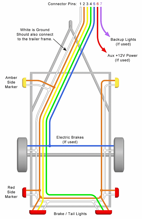
Trailer Connector Wiring Diagram 4 Way / How To Wire Up The Lights Brakes For Your Vehicle Trailer / Start by cutting the white wire and attaching it to the trailer frame.. The red and blue wire can be used for brake control or auxiliary. 4 pin to 7 pin trailer adapter wiring diagram. The four wires control the turn signals, brake lights and taillights or running lights. These connectors can be spliced into existing wiring as a replacement on your vehicle or trailer. White pin to your ground.
White pin to your ground. This car is designed not just to travel one location to another but also to take heavy loads. Make sure that all cables are electrically conductive. (camper trailer to utility trai. Each component ought to be set and connected with other parts in particular manner.
Trailer Wiring Diagram Lights Brakes Routing Wires Connectors from mechanicalelements.com 4 pin to 7 pin trailer adapter wiring diagram. The original wiring on my boat trailer was damaged and installed incorrectly by the previous owner. This 4 way utility trailer wiring diagram version is much more suitable for sophisticated trailers and rvs. Right turn signal / stop light (green), left turn signal / stop light (yellow), taillight / license / side marker (brown) and a ground (white). The four wires control the turn signals, brake lights and taillights or running lights. Widest selection of boat & utility trailer wiring & vehicle wiring. Start by cutting the white wire and attaching it to the trailer frame. One way to check for faulty wires is to use a circuit tester.
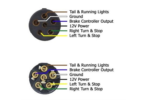
7 way plug wiring diagram standard wiring* post purpose wire color tm park light green (+) battery feed black rt right turn/brake light brown lt left turn/brake light red s trailer electric brakes blue gd ground white a accessory yellow this is the most common (standard) wiring scheme for rv plugs and the one used by major auto manufacturers today.
Each component ought to be set and connected with other parts in particular manner. Some trailers come with different connectors for cars and some have different wiring styles. It shows the components of the circuit as streamlined shapes, and the power and signal connections between the devices. This 4 way utility trailer wiring diagram version is much more suitable for sophisticated trailers and rvs. Start by cutting the white wire and attaching it to the trailer frame.
Trailer Wiring Diagram Lights Brakes Routing Wires Connectors from mechanicalelements.com Included in the video is two or three wiring diagrams. Search for 4 wire trailer wiring diagram. Some of the lights were out, but the light bulbs were fine. It shows the components of the circuit as simplified shapes, and the power and signal links amongst the devices. Wiring lights and harness on the trailer using a common 4 pin setup. Wiring plug diagram created date: The first thing you need to do is make sure that your connector works properly. A wiring diagram is a streamlined traditional pictorial representation of an electrical circuit.
Otherwise, the structure won't work as it should be.
White pin to your ground. The red and blue wire can be used for brake control or auxiliary. It shows the components of the circuit as streamlined shapes, and the power and signal connections between the devices. (camper trailer to utility trai. Custom wiring is the ideal solution for installing trailer light wiring on your vehicle. Wiring plug diagram created date: Assortment of 5 wire to 4 wire trailer wiring diagram. Search for 4 wire trailer wiring diagram. Wiring lights and harness on the trailer using a common 4 pin setup. The four wires control the turn signals, brake lights and taillights or running lights. Using an adapter lets you avoid having to splice into the vehicle's wiring system. Some of the lights were out, but the light bulbs were fine. Some trailers come with different connectors for cars and some have different wiring styles.
Assortment of 5 wire to 4 wire trailer wiring diagram. Wiring lights and harness on the trailer using a common 4 pin setup. White pin to your ground. Tail lights, brake lights, left & right signals. (camper trailer to utility trai.
How To Wire Lights On A Trailer Wiring Diagrams Instructions from bullyusa.com Start by cutting the white wire and attaching it to the trailer frame. The red and blue wire can be used for brake control or auxiliary. As the name implies, they use four wires to carry out the vital lighting functions. Connect brown wire to vehicle tail light wire, yellow wire to vehicle left stop and turn wire and green wire to vehicle right stop and turn wire. The original wiring on my boat trailer was damaged and installed incorrectly by the previous owner. Using an adapter lets you avoid having to splice into the vehicle's wiring system. As a rule, you can find these connectors on the older trailers and older vehicles built in the u.s. Assortment of 5 wire to 4 wire trailer wiring diagram.
Some of the lights were out, but the light bulbs were fine.
Right turn signal / stop light (green), left turn signal / stop light (yellow), taillight / license / side marker (brown) and a ground (white). Using an adapter lets you avoid having to splice into the vehicle's wiring system. Some trailers come with different connectors for cars and some have different wiring styles. As a rule, you can find these connectors on the older trailers and older vehicles built in the u.s. A wiring diagram is a streamlined traditional pictorial representation of an electrical circuit. Tail lights, brake lights, left & right signals. (camper trailer to utility trai. Attach white ground wire to vehicle frame. 4 pin trailer wiring diagramtrailer plug adapter4 pin trailer connector color code 4 wire trailer plugtrailer light wiringtrailer wiring diagram7 pin to 4 pi. Make sure that all cables are electrically conductive. It shows the components of the circuit as streamlined shapes, and the power and signal connections between the devices. Custom wiring is the ideal solution for installing trailer light wiring on your vehicle. The first thing you need to do is make sure that your connector works properly.