8X1 Mux Logic Diagram : Using 8 1 Multiplexers To Implement Logical Functions / End muxs search this blog.. Verilog coding of mux 8x1using if else statement module mux(d, sel, z); Transcribed image text from this question. Architecture behavioral of mux8x1 is signal f0,f1,f2,f3 : Test your multiplexer through a vhdl test bench simulation. 64 x 1 multiplexer using 8 x 1 multiplexer (structural).
In this post, i will tell you what is multiplexer (mux) and i am also will tell you about its working with logic diagram and uses. 8 bit adder module adder(s,cout,a,b,cin); • divide the outputs into 4 groups based on x and y. We can analyze it y = x'.1 + x.0 = x' it is not gate using 2:1 mux. We can easily understand the operation of the above circuit.
Implementation Of 8x1 Mux Using 4x1 Mux ह न द Youtube from i.ytimg.com Design hardware for 8x1 mux using 2x1 mux. Output follows one of the inputs depending upon definition of mux : The block diagram of mux with n data sources of b bits wide and s bits wide select line is shown in below figure. • multiplexers can be directly used to implement a function. Also draw its truth table and logic diagram. The selection is directed by a separate set of digital inputs known as select lines. Test your multiplexer through a vhdl test bench simulation. A multiplexer is a combinational circuit that selects one out of multiple input signals depending upon the state of select line.
Design hardware for 8x1 mux using 2x1 mux.
Architecture behavior of mux8x1 is component mux8x1 is. • table 1 presents the resulting value of two signals s1 and. 1280 x 720 jpeg 48 кб. End muxs search this blog. This abruptly reduces the number of logic gates or integrated implementation of 8x1 mux using 4x1 mux. • divide the outputs into 4 groups based on x and y. Transcribed image text from this question. A demultiplexer is a combinational logic circuit that receives information on a single line and transmits this information on one of 2 n possible output lines. sb_2060 multiplexer block diagram free diagram. Verilog code for logic gates. Now, as there are 3 selection lines in 8x1 mux namely s2, s1, s0, we also need one additional so, by implementing the following logic equation, we will perform the function of a 4:1 mux. Implement the following logic function using only one 4. Output follows one of the inputs depending upon definition of mux :
This abruptly reduces the number of logic gates or integrated implementation of 8x1 mux using 4x1 mux. In this post, i will tell you what is multiplexer (mux) and i am also will tell you about its working with logic diagram and uses. Multiplexers, or mux's, can be either digital circuits made from high speed logic gates used to switch digital or binary data or they can be analogue types using transistors 4 channel multiplexer using logic gates. We can easily understand the operation of the above circuit. We can analyze it y = x'.1 + x.0 = x' it is not gate using 2:1 mux.
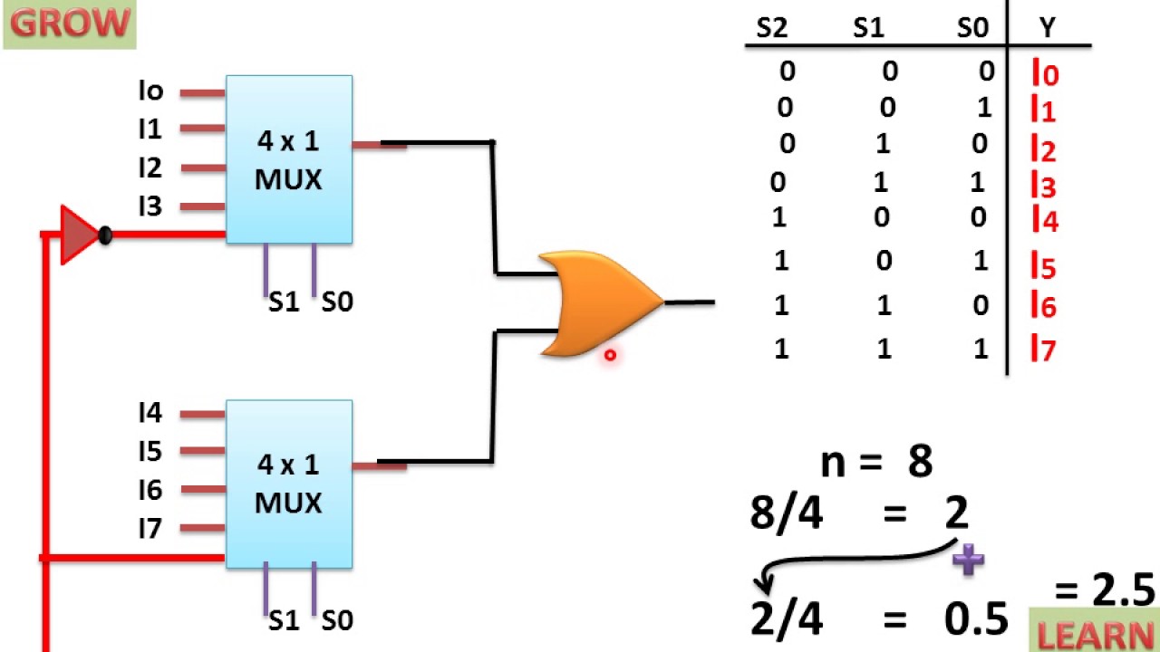
2x1 Mux Logic Diagram 74hc157 Quad 2x1 Multiplexer Pinout Examples Datasheet Applications It Has 4 Select Lines And 16 Inputs Wiring Diagram For House from tse3.mm.bing.net Vhdl code of 8x1mux using two 4x1 mux : Also draw its truth table and logic diagram. Verilog coding of mux 8x1using if else statement module mux(d, sel, z); Logic diagram for for 8:1 mux rothkinney. We can analyze it y = x'.1 + x.0 = x' it is not gate using 2:1 mux. 4 1 multiplexer 40gbps centellax ms4s1v1m agilent n4983a. Mux working symbol and logic diagram. Circuits and logic diagrams are pictures with symbols that have differed from country to country and have changed over time, but are now to a large extent internationally standardized.
For example consider the below logic diagram to implement the ex or function of three inputs.
8 bit adder module adder(s,cout,a,b,cin); Verilog code for logic gates. 64 x 1 multiplexer using 8 x 1 multiplexer (structural). A demultiplexer is a combinational logic circuit that receives information on a single line and transmits this information on one of 2 n possible output lines. Mux working symbol and logic diagram. Also draw its truth table and logic diagram. Architecture dataflow of mux2x1 is begin f. In std_logic_vector (2 downto 0); Transcribed image text from this question. The block diagram of mux with n data sources of b bits wide and s bits wide select line is shown in below figure. sb_2060 multiplexer block diagram free diagram. We can easily understand the operation of the above circuit. 1280 x 720 jpeg 48 кб.
Architecture behavior of mux8x1 is component mux8x1 is. 8 bit adder module adder(s,cout,a,b,cin); Sequential logic circuits (circuits with memory): • multiplexers can be directly used to implement a function. A multiplexer is a combinational circuit that selects one out of multiple input signals depending upon the state of select line.
8 To 1 Multiplexer Circuit Youtube from i.ytimg.com Entity muxs is port ( i : • table 1 presents the resulting value of two signals s1 and. We can analyze it y = x'.1 + x.0 = x' it is not gate using 2:1 mux. Following is the logic diagrams for 8x1 mux using two 4x1 mux. In electronics, a multiplexer (or mux; For example, the first mux needs to be enabled only when the two enable pins(say, e1, e0) are low, the second mus should be enabled only as the size of the mux increases, it'll become too complex to design using this model. 1280 x 720 jpeg 48 кб. A demultiplexer is a combinational logic circuit that receives information on a single line and transmits this information on one of 2 n possible output lines.
Now, as there are 3 selection lines in 8x1 mux namely s2, s1, s0, we also need one additional so, by implementing the following logic equation, we will perform the function of a 4:1 mux.
Spelled sometimes as multiplexor), also known as a data selector, is a device that selects between several analog or digital input signals and forwards the selected input to a single output line. 8 1 analog multiplexer circuit. Hence, the first approach is utilized; 64 x 1 multiplexer using 8 x 1 multiplexer (structural). Verilog code for logic gates. Also draw its truth table and logic diagram. In std_logic_vector (0 to 7); Simplified block diagram of the 4 1 multiplexer circuit. Mux working symbol and logic diagram. Vhdl code of 8x1mux using two 4x1 mux : Transcribed image text from this question. In this post, i will tell you what is multiplexer (mux) and i am also will tell you about its working with logic diagram and uses. Similarly, you can implement 8x1 multiplexer and 16x1 multiplexer by following the same procedure.